Micro Relay 4 Pin Diagram

4 Pin 12v 20amp Automotive Micro Relay Make And Break Car Van Bike Y1 Ebay
Micro Relay 4 Pin 12v 20a With Diode Car Automotive Auto Micro Relay Make And Break Car Van Bike Boat

Micro Relay 4pin 12v 20a
12 Volt Car Relays Used In Automotive Industry

4 Pin Relay Diagram 4 Pin Relay Wiring 4 Pin Relay Animation 4 Pin Relay Connection Youtube
Automotive Relay Guide 12 Volt Planet
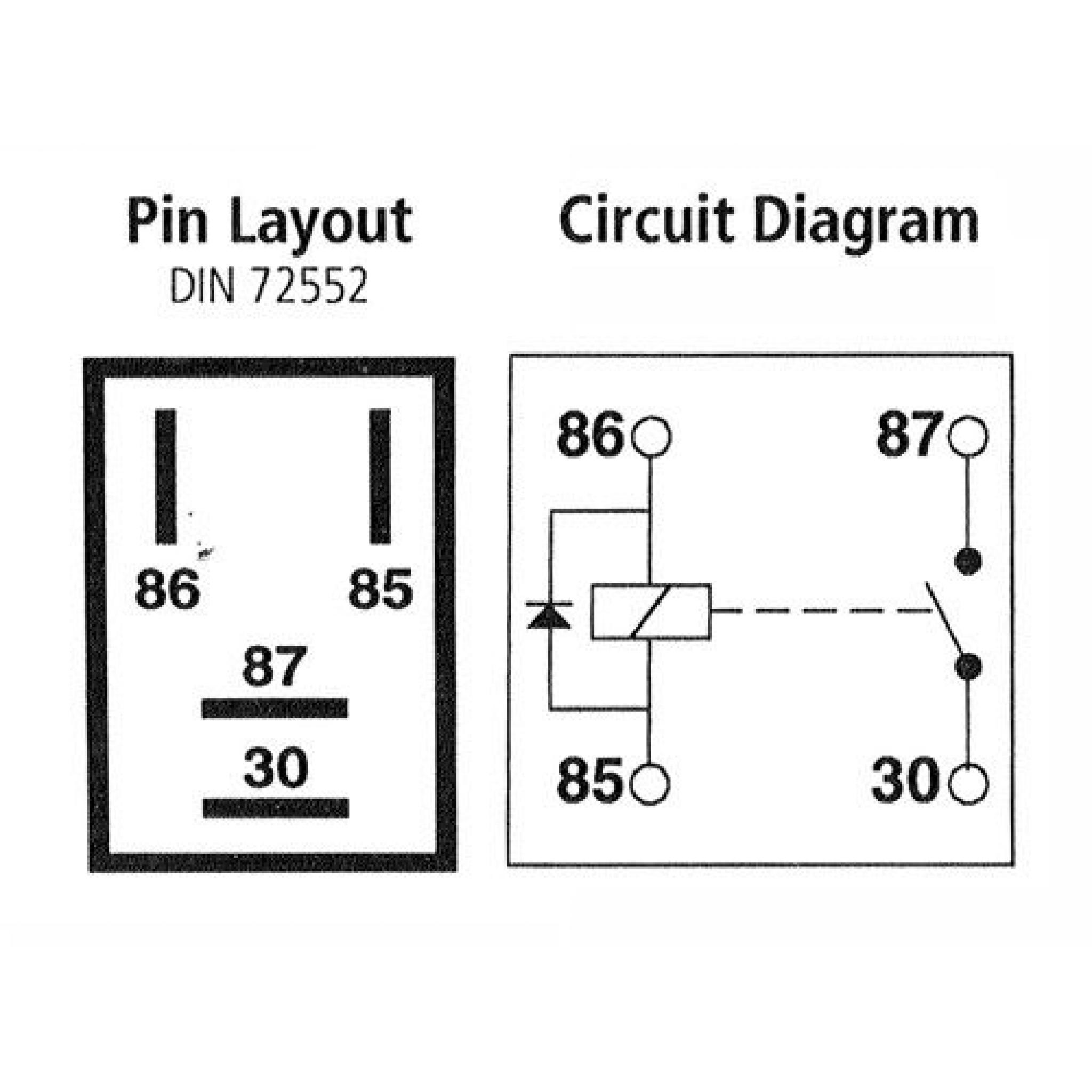
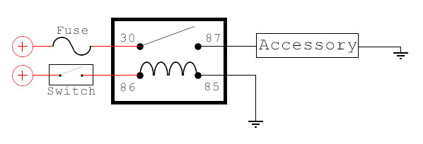
When a relay contact is closed there is a closed contact when the relay is not energized.
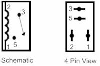
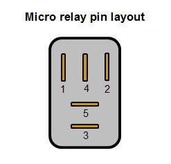
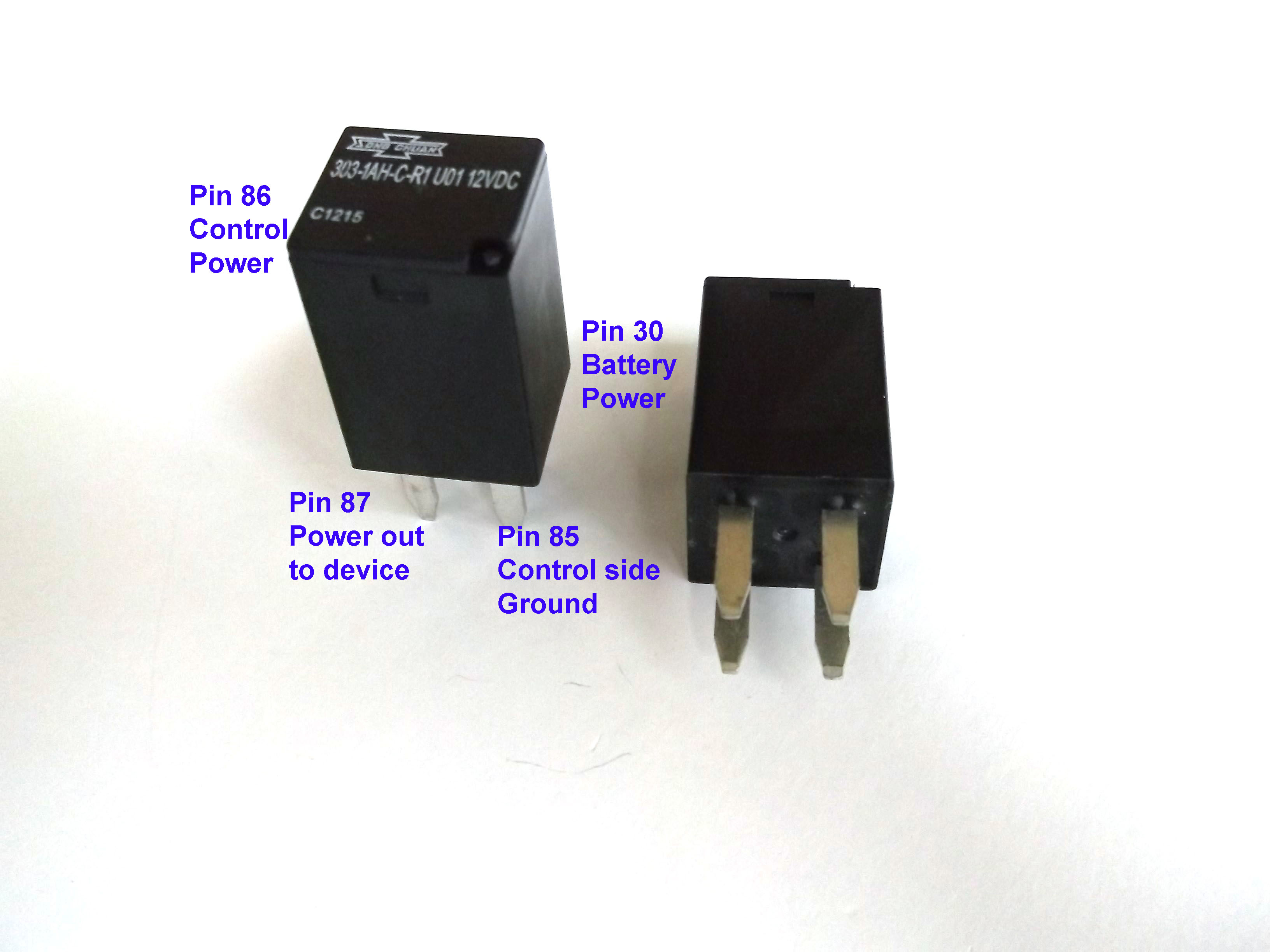
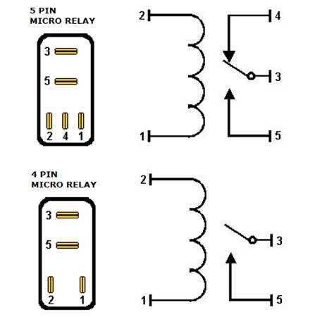
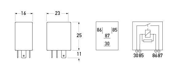
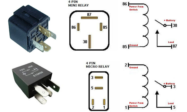
Micro relay 4 pin diagram.

Micro Mini And Pcb Relays

4 Pin Diode Protected Automotive Type 25amp 12v Micro Relay Alt Ry2842d 09
Denso 4 Pin Micro Relay Pinout Toyota Nation Forum

Narva Micro Relay 12v 4pin 20a Autobarn

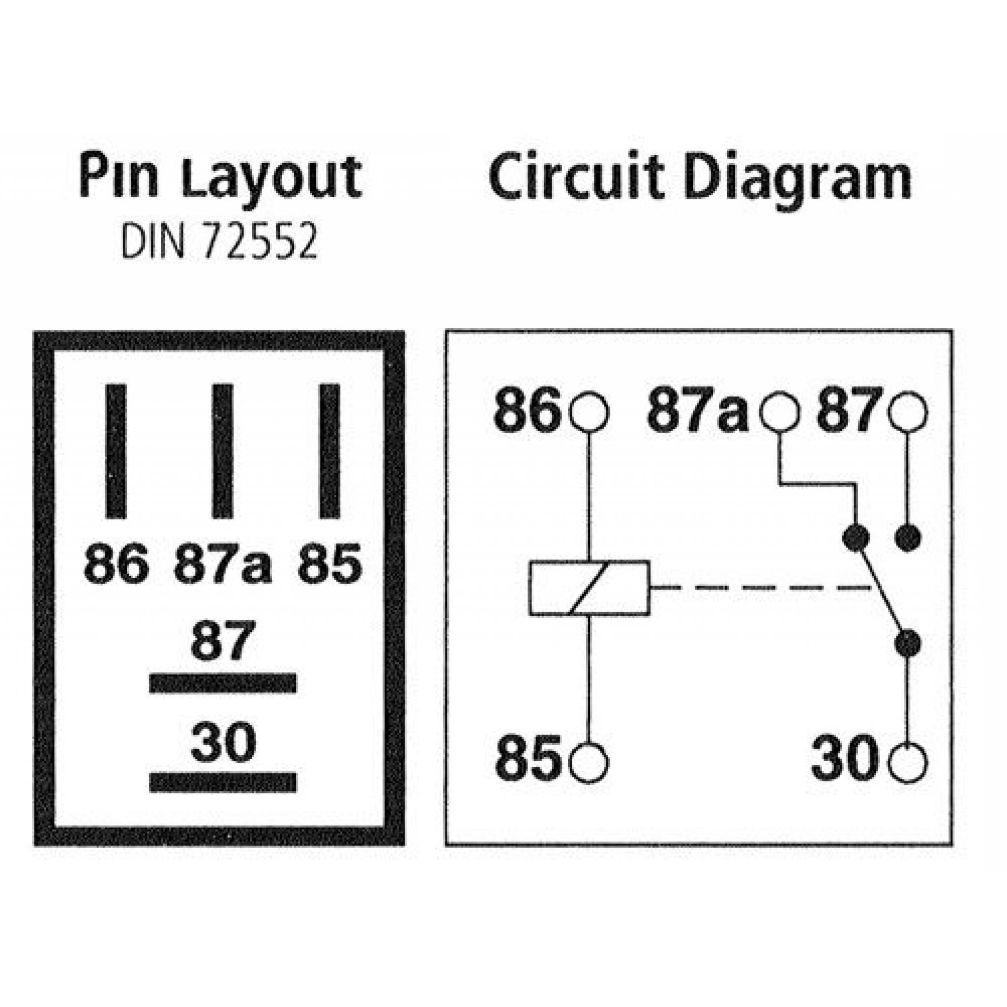
Denso Relay 4 Pin Wiring Diagram Benign Blog

Rs 9106 Relay Normally Open Free Diagram
Diy Bussmann Rtmr Fuse Block Part 4 Wiring And Schematics Bodenzord
Motorcycle Relays Panasonic Mitsuba
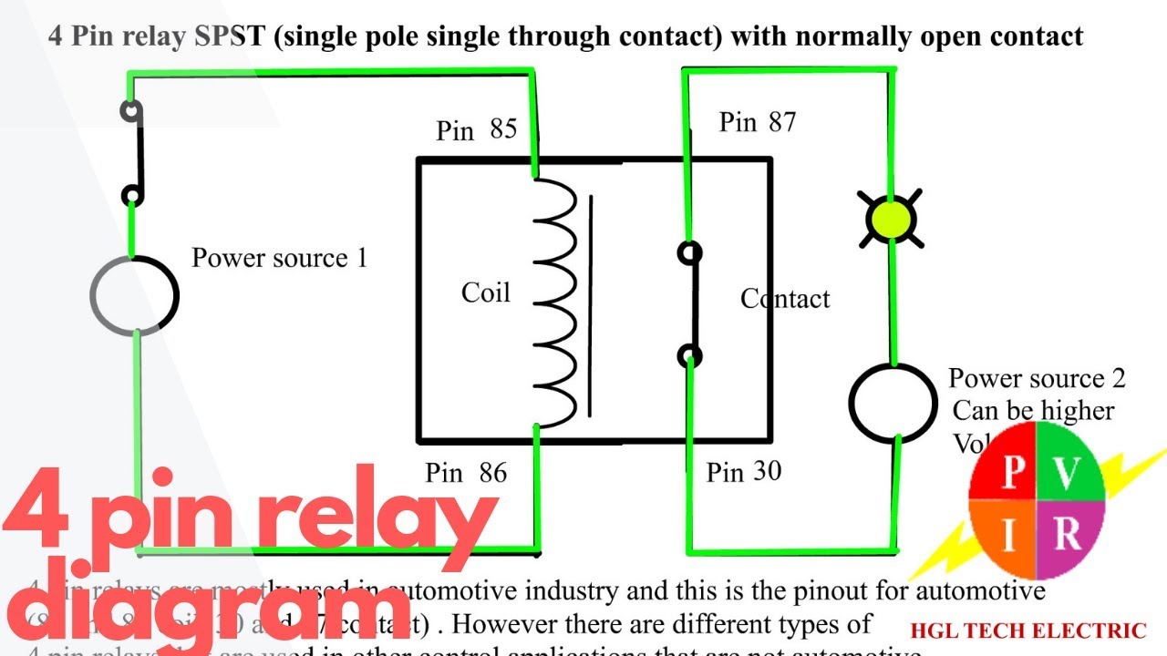
Diagram 5 Pin Wiring Diagram Full Version Hd Quality Wiring Diagram Diagramland Cigarren Ullrich De
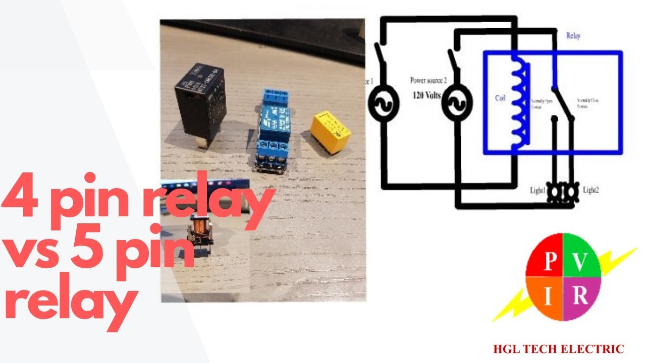
4 Pin Relay Vs 5 Pin Relay 4 Pin Relay And 5 Pin Relay Wiring Diagram 5 Pin Relay Wiring Youtube
Https Www Consulab Com Files Electricaldshandoutv20181r1reduced Pdf

Bosch 4 Pin Relay Wiring Diagram For Doorbell Symbols Car Relay Diagram Electrical Wiring Diagram

Amazon Com Omron Gm 4 Pin Relay 15328866 High Power 4 Terminal Multi Use Relay 8385 Pack Of 3 Industrial Scientific
Micro Relay 5 Pin Changeover 12v 20a Car Automotive Auto Micro Relay Make And Break Car Van Bike Boat

4 Pin 30a 12v Spst Micro Relay 10 Pack Genssi

Usb Wire Diagram Schematic Micro Wiring Connector Colors To With Volovets Info In 2020 Electrical Diagram Circuit Diagram Automotive Electrical

Hella 12v 4 Pin Relay Normally Open With 15 Amp Fuse Mounting Bracket Form A
Micro Relays To Drive Cooling Fans Ls1tech Camaro And Firebird Forum Discussion
Https Encrypted Tbn0 Gstatic Com Images Q Tbn 3aand9gcrkf7c Nrre8vuqffy Sbiyfxgcjzkewurnellpq0hp09pg Ngt Usqp Cau
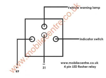
Led Indicator Flasher Relay 12 Volt 4 Pin 30w Mobile Centre

2008 Crv Ac Issues Honda Civic Forum

5 Pin 40a Relay And Wire Harness Spdt 12v 5 Pack Genssi
12v 4 Pin Normally Open Micro Relay 20a Resistor
2010 Ac Not Working Honda Civic Forum
Source : pinterest.com
